


Dark-Field Illumination For Line Scan Camera

Hi friends, this week I will talk about machine vision.
This is a post about light. Specifically, light directions. It is difficult to exhaust the properties of light. 😊 Therefore, this will be one of a series.
It was originally written one year ago, before the start of this channel. A result of brainstorming as a pre-content creator. I decided to focus on machine vision. However, the Book Club and Business sections grow much faster. Machine vision, and Large-Scale Machine Vision specifically, is my niche, and I will give them more chances to reach broader audiences.
Let’s dive in.
Dark-Field Illumination
The dark-field technique is used to enhance structural contrast. Scratches, dents, bumps, and plateaus. Their contours stand out more from a flat surface background.
Dark-field illumination is one of the most important lighting techniques in machine vision for surface structure inspection. The following graph shows the difference between bright-field and dark-field illumination setups.

When almost all light rays emitted from the illumination get reflected (by the object's surface) towards the camera, it is called a bright-field. The other way is called dark-field. In the normal use case (matrix camera), it is easy to differentiate the two setups. We can use the “W” method.
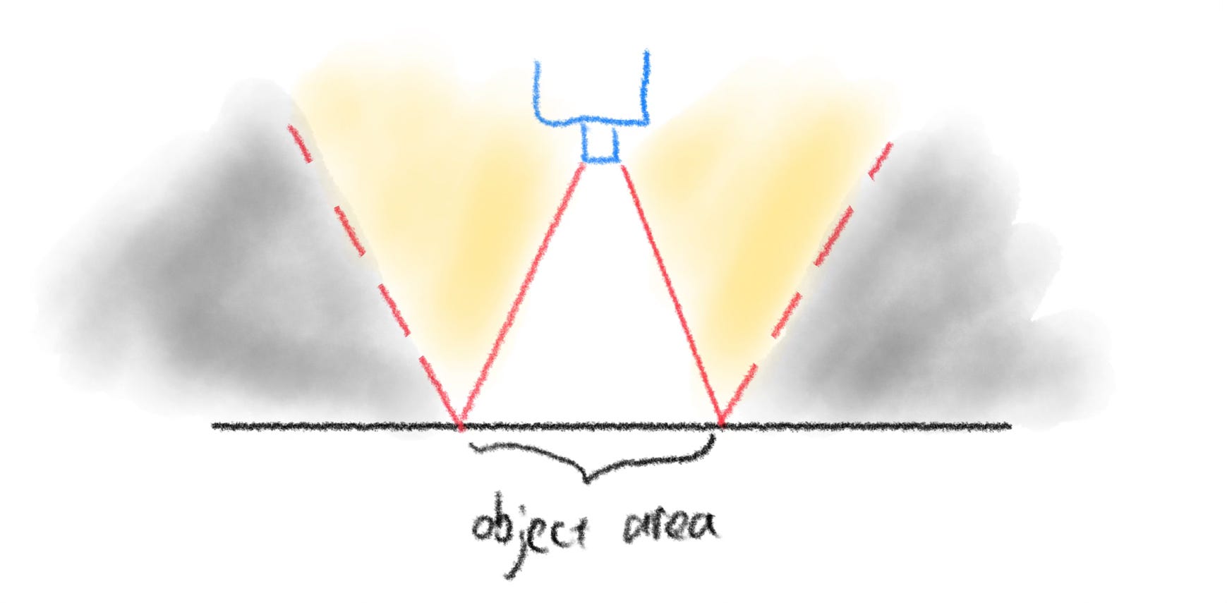
The camera field of view and its imaginary specular reflection form a “W” shape. Any light source falls inside this “W” shape is bright-field illumination, and when it falls outside it will be dark-field illumination.
Dark-Field Illumination For Line Scan Camera
Determining dark-field for a line scan camera uses the same principle. I.e., how much light gets reflected back from a flat surface to the camera?
First, what is a line scan camera?
Line scan cameras are industrial cameras that are particularly well-suited to applications involving objects with large surface areas, high-speed inspection, or small defect detection. They work by capturing an image of an object one line at a time, as opposed to capturing the entire image at once like a traditional camera. I have a dedicated post talking about line scan cameras, see what-is-line-scan-camera
The dark-field setup for line scan is very flexible. Let’s first discuss how to differentiate dark-field and bright-field.
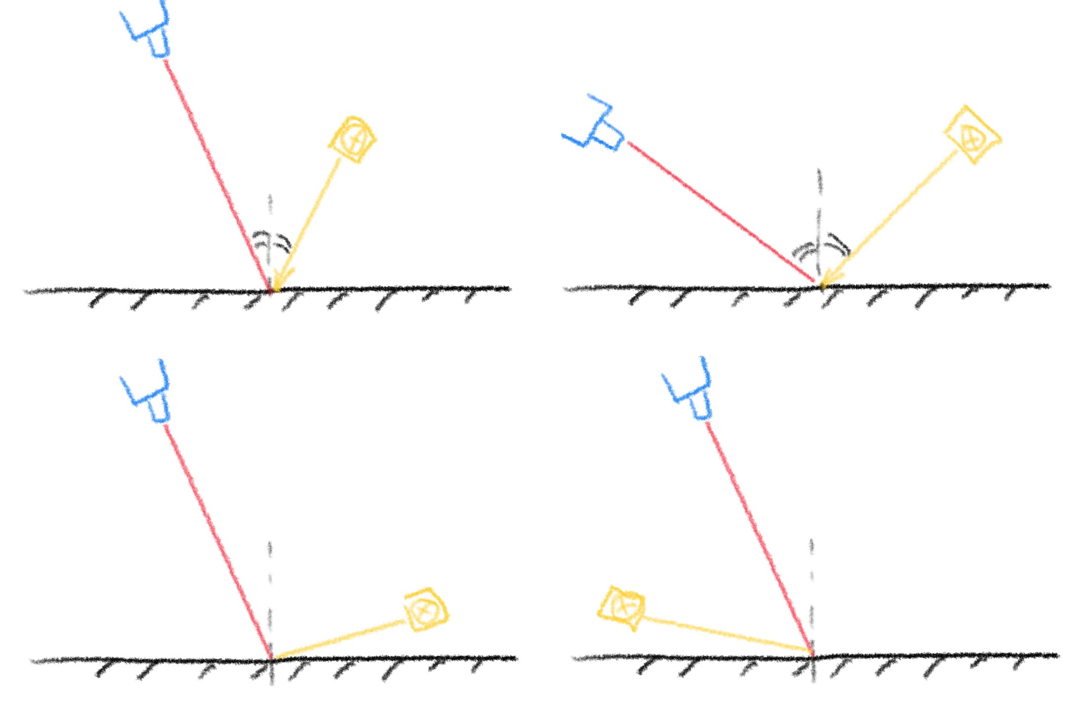
As the camera field of view is a single line, in most illumination scenarios, light rays bounce outside the camera capturing range. Only when the incident beam equals the viewing angle does it form the true bright-field. The rest are dark-fields.
This leads to the two major scenarios of dark-field.
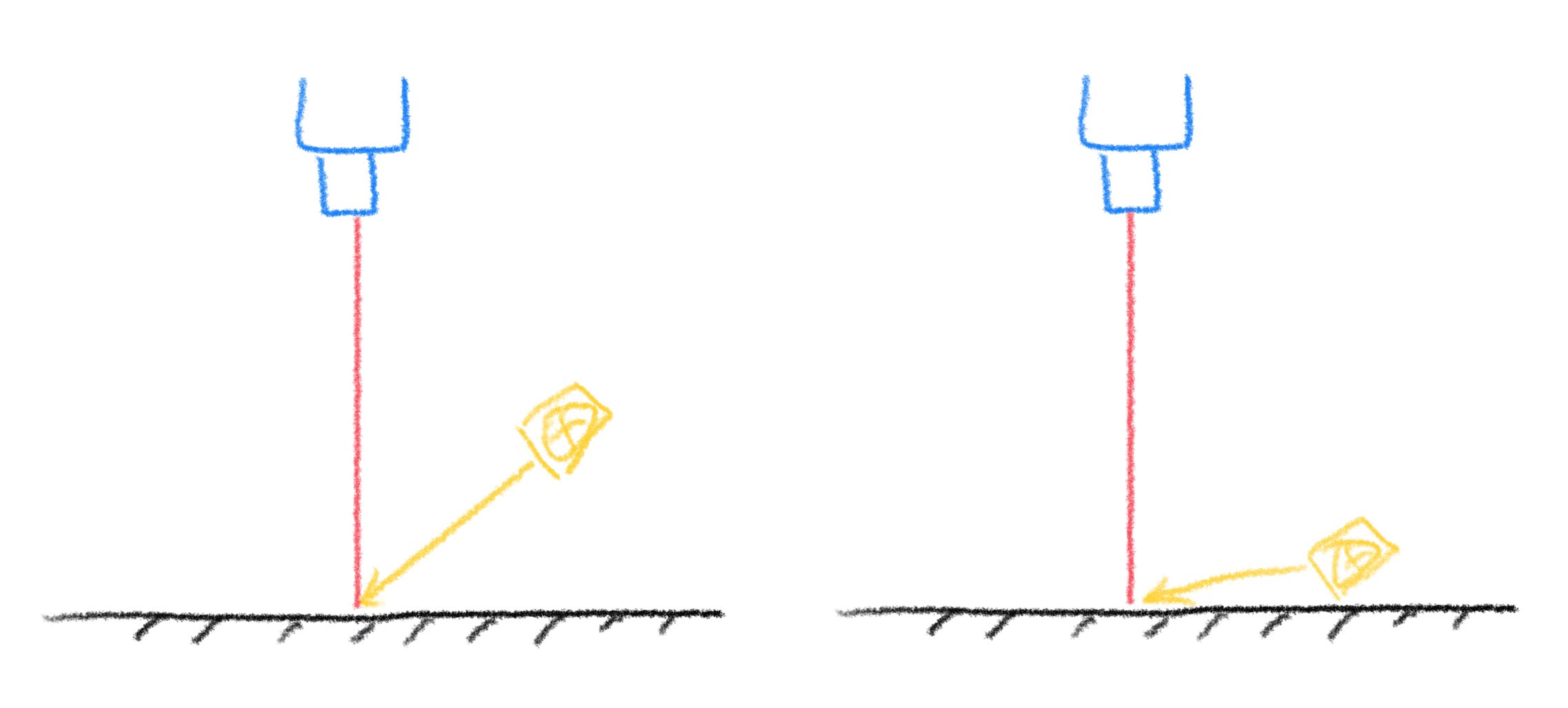
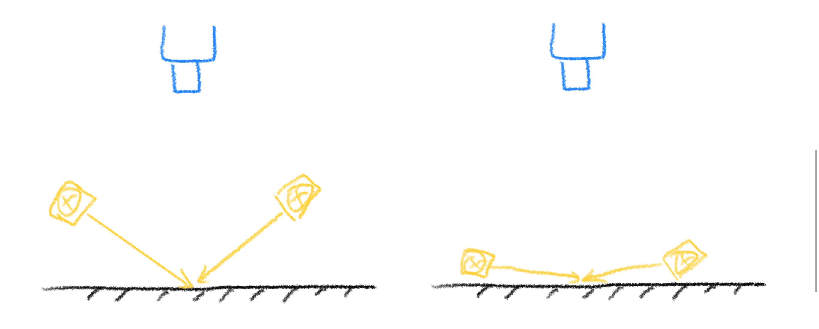
Setup 1: High-Angle Dark-Field
Advantage: gives rich and balanced details between geometrical features and material features.
Problem: low contrast for any type of features.
The theme of this setup is balance. If a use case doesn’t allow two illumination sets due to limited space, this setup covers all the features you need. However, the same reason will lead to substantially more image processing efforts.
Setup 2: Low-Angle Dark-Field
Low-angle dark-field illumination is more common for a very simple reason. It highlights geometrical features. In many detection-only use cases, it is a must-to-have setup. However, it is rarely used alone.
Advantage: strong contrast at locations where there are height variations.
Problem 1: exaggerated structural effects and coarse image quality.
The effect of this setup is similar to applying a gradient filter along light emition direction. The lower the angle, the bigger the filter window size. Details are lost.
Problem 2: potential smaller defects are overshadowed by the adjacent bumps.
Problem 3: inefficient use of light source power.
Without going into details, the efficiency of the same light source is coarsely dependent on the incident angle. Shown in the equation below.
Middle angle like 45 degrees will achieve around 70% efficiency, while extreme low angle like 10 degrees can only reach 17% efficiency.
Problem 4: decrease overall system mechanical stability against vibration and tolerance.
Due to the above Problem 3, the lower the angle, the less tolerant of misalignment of line camera view and light field.
Each setup focuses on certain information. Each setup ignores lots of other information. Therefore, designing the illumination is an engineering process to balance many parameters while bring the highest contrast of wanted features. This post mainly focuses on the light angle. I purposely omit the material reflection reaction. In the following post, we will cover material properties to look at the same problem from a different angle.